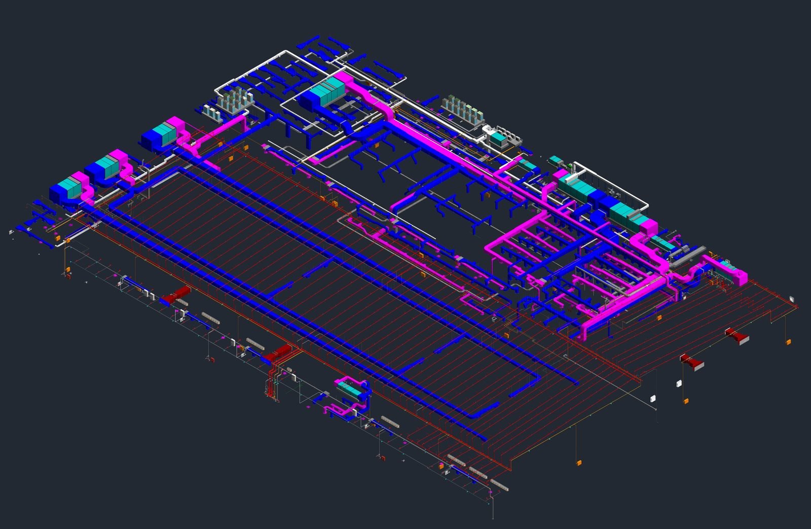

A steel model can look finished at every zoom level and still not be fabricable. The column is where it should be, the beam frames in, the render is convincing, and there is no end plate, no bolt, no weld and no assembly mark. That model is useful for coordination. A fabricator cannot cut steel from it.
The difference has a name (LOD 400) and contracts increasingly ask for it. They do not always mean the same thing by it. This is what the definition actually requires, what it means inside a Tekla model, and the checks we run before a steel model leaves the office.
What the LOD Specification says
The LOD Specification published by BIMForum defines levels of development. It is careful to separate two ideas that are easy to confuse: level of detail is how much detail is included in an element, while level of development is how far the element's geometry and attached information have been thought through, and therefore how far the rest of the team can rely on them.
| LOD | What the element carries (paraphrased) | What it means for a steel member |
|---|---|---|
| 300 | Quantity, size, shape, location and orientation can be measured. | The member is sized and placed. Connections are not modelled. |
| 350 | The same, plus its interfaces with adjacent or dependent elements. | Connection zones, slab edges, embeds and service clearances are resolved. |
| 400 | Detail sufficient for fabrication, assembly and installation. | Plates, bolts, welds, copes and stiffeners, grouped into assemblies with marks. Drawings and NC files come from it. |
| 500 | A field-verified representation of the as-constructed condition. | A record of what was built, not a higher design level. |

LOD 400 is a responsibility, not a graphic level
Nobody can model a connection to fabrication level without knowing who designs it. Under ANSI/AISC 303-22 §3.2.3, the engineer of record states, connection by connection, one of three options: the engineer shows the complete connection design; an experienced detailer selects or completes it from reference information; or a licensed engineer working for the fabricator designs it. Under the second and third options the design documents must also give the forces, whether they are service or factored loads, and whether the design is LRFD or ASD.
So an LOD 400 steel model sits with whoever holds the connection design and the fabrication information, usually the detailer working for the fabricator, against design criteria the engineer has published. A consultant's model that stops at LOD 350 is not a failure; it is often exactly the right hand-over point.

What a fabrication-ready Tekla model carries
- Parts and assemblies. Every plate, stiffener, cleat and fitting is a part, and every part belongs to one assembly. A loose part is a piece nobody will fabricate.
- Bolts as objects. Standard, grade, diameter, length, hole type and whether the bolt is pretensioned are attributes of the bolt, not notes on a sheet, so the bolt list is counted, not typed.
- Welds as objects. Type, size and whether the weld is made in the shop or on site. Site welds drive the erection sequence and access, so they are decided in the model, not discovered on the frame.
- Cuts, copes and holes. Every cope and every hole for a service, resolved against the MEP model at LOD 350 first.
- Numbering. Identical assemblies share one mark, and the numbering is run before the drawings are made, not after.
- Material and finish. Grade, coating system and the faying surfaces of slip-critical joints, whose surface treatment has to match the slip class the design assumed.
The model is the source of every output
At LOD 400 the general arrangement drawings, the assembly and single-part drawings, the bolt and material lists and the NC files are all produced from the model. An edit made on a drawing and not in the model is an edit the next revision erases. NC data for saws, drill lines and cutting machines is usually exported in the DSTV format, the NC interface published by the German steel construction association; the model goes to the other disciplines as IFC, the open schema standardised as ISO 16739-1.

The checks before a model is issued
| Check | What it catches | When |
|---|---|---|
| Clash run, steel against MEP and architecture, at the project's clearance rules | A cope, a bolt head or an erection clearance running through a duct | Before numbering |
| Assembly check: no loose parts, one mark per identical assembly | A plate welded to nothing; two marks for one assembly | Before drawings |
| Bolt check: grip, length, edge distance, pretension flag | A bolt that is too short or that no wrench can reach | Before drawings |
| Weld check: every weld has a size, a type and shop or site | A site weld nobody planned access for | Before drawings |
| Drawing against model revision | A drawing edited by hand | At every issue |
| Erection check: lifting points, site splices, sequence | A piece too heavy or too long for the lift plan | Before issue |

When LOD 400 is the wrong thing to ask for
Not every element needs it, and asking for it everywhere costs time and buys nothing. A coordination model at LOD 350 is the right level for resolving MEP zones before steel is detailed. Architectural finishes in a steel package, or temporary works nobody will fabricate from the model, do not need fabrication detail. The LOD Specification is built to be used element by element: the BIM execution plan should set the LOD for each element at each stage, name who is responsible for it, and name the exchange format.
This is how we work on steel: connection design and Tekla detailing in one office, from the design criteria to the fabrication drawings, the NC files and the erection sequence, on packages such as the MDLBEAST event bridge and the Siemens Energy hub. See Steel structures for the scope.
Frequently asked questions
Is LOD 400 the same as a model with a lot of detail?
No. The LOD Specification separates level of detail (how much is drawn) from level of development: how far the element has been thought through and can be relied on. A heavily detailed connection nobody has checked against the design criteria is not LOD 400.
Can the design consultant deliver LOD 400 steel?
Only where it holds the connection design and the fabrication information. AISC 303-22 §3.2.3 lets the engineer design the connection, have a detailer complete it from criteria, or delegate it to the fabricator's licensed engineer. The LOD 400 model belongs with whoever holds that responsibility.
Is LOD 500 a more detailed model than LOD 400?
No. LOD 500 describes a field-verified representation of what was built. It is about verification on site, not about more detail.
What should the BIM execution plan say about LOD?
A model element table: the LOD of each element at each stage, who is responsible for it, and the exchange format, IFC for coordination, the native model with DSTV NC files for fabrication.